
Therefore, the improvement of such circuits without weakening the characteristics is of prime importance to the VLSI industry. The total clock related power consumption in synchronous VLSI circuits can be divided into three major factors: power consumption in the clock network, power consumption in the clock buffers, and power consumption in the flip-flops.
An edge triggered flip flop. portable#
In portable systems, very low power consumption is desired in order to increase battery life. Power consumption of VLSI chips is becoming an increasingly critical problem as modern VLSI circuits continue to grow and technologies evolve. Currently, several VLSI design implementations are described in CMOS technology. In the past, the major concerns of the very large scale integrated (VLSI) engineers were area, performance, cost and reliability power considerations were mostly of only secondary importance. Keywords DETFF, delay, PDP, performance, power consumption, throughput. The DETFF based shift registers are simulated with different clock frequencies and the performance of the shift registers are evaluated by observing the average power, delay and PDP. As a result, power consumption is reduced, making DET flip-flops desirable for low power applications. Although the clock frequency is determined by the system specifications, the usage of DET flip-flops can reduce the clock frequency to half of its original value for the same data throughput. Double Edge Triggered Flip Flops stores data on both the rising edge and falling edge of a clock signal.
An edge triggered flip flop. serial#
This paper provides an efficient design and analysis of Serial In Serial Out (SISO), Serial In Parallel Out (SIPO), Parallel In Serial Out (PISO) and Parallel In Parallel Out (PIPO) shift registers using High Performance Double Edge Triggered D-Flip flop (DETFF). International Journal of Engineering Research & Technology (IJERT)ġII Year M.Tech, VLSI Design, Sathyabama University, Chennai.Ģ Asst.Professor, Department of ECE, Sathyabama University, Chennai.ģ Principal, Jeppiaar Institute of Technology, Kunnam, Chennai. To avoid this udesirable operation, the clock pulse must have a time duration that is shorter than the propegation delay time of the flip-flop.2GHz High Performance Double Edge Triggered D-Flip Flop Based Shift Registers In 32NM CMOS Technology It is very important to realize that because of the feedback connection in the JK flip-flop, a CP pulse that remains in the 1 state while both J and K are equal to 1 will cause the output to complement again and repeat complementing untill the pulse goes back to 0. In either case the output of the flip-flop is complemented.

If Q' = 1, the output of the lower of the lower AND gae becomes 1 and the flip-flop is set. Thus if Q = 1, the output of the upper AND gate becomes 1 upon application of the clock pulse and the flip-flop is cleared. When both J and K are 1, the input pulse is transmitted through one AND gate only the one whose input is connected to the flip-flop output that is presently equal to 1. Similerly output Q' is ANDed with J and CP inputs so that the flip is set with a clock pulse only when Q' was previously 1. Output Q is ANDed with K and CP inputs so that the flip-flop is cleared during a clock pulse only if Q was previously 1.

A J-K flip-flop constructed with two crossed coupled NOR gates and two AND gates. When both inputs J and K are equal to 1, the flip flop switches to its complement state, that is, if Q = 1, it switches to Q = 0 and vice versa. The input mark J is for set and the input mark K is for reset. The difference is that the J-K flip-flop has no invalid state as does the S-R flip-flop.

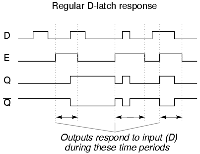
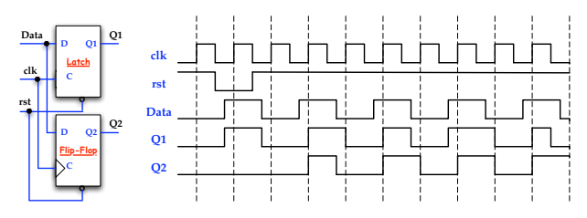
The J and K designations for the inputs have no known significance except that they are adjucent letters in the alphabet.The function of J-K flip-flop is identical to that of the S-R flip-flop in the SET, RESET and no-change conditions of operation. The J-K flip-flop is versatile and is a widely used type of flip-flop. An edge-triggered flip-flop changes state either at the positive edge (riging edge) or at the negative edge (falling edge) of the clock pulse and is sensitive to its inputs only at this transition of the clock. Here synchronous means that the output changes state only at a specific point on a triggering input called the clock (CLK), which is designated as a control input C that is, changes in the output occur in synchronization with the clock. Flip-flops are synchronous bistable devices, also known as bistable multivibrators.


 0 kommentar(er)
